

 English - Singapore
 English - United States
 Italiano - Italia
 日本語 - 日本
 한국어 - 대한민국
 Svenska – Sverige

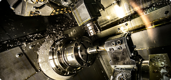
Multi-axis machining has reshaped modern manufacturing, allowing machine shops around the globe to produce complex components with fewer setups, while achieving higher levels of accuracy and efficiency.
Whether you’re running a 4-axis rotary application or a fully simultaneous 5- or 6-axis process, these machines can significantly improve both productivity and profitability.
However, greater capability also brings greater complexity. Even experienced programmers can run into issues that result in scrapped parts, wasted material, damaged tooling, machine downtime, and costly production delays.
In this article, we’ll break down the seven most common programming mistakes in multi-axis machining — and explain how simulation and verification with Vericut can help you avoid them.
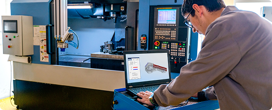
What is Multi-Axis Machining?
Multi-axis machining solutions use CNC equipment that can move either the cutting tool or the workpiece along more than the standard three linear axes (X, Y and Z).
By introducing rotary motion through additional axes (A, B or C), manufacturers can machine complex surfaces and geometries in fewer setups, often completing parts in a single, continuous operation.
From aerospace turbine blades to bespoke medical implants, multi-axis machining enables the accurate production of components that would otherwise be extremely difficult — or impossible — to manufacture.
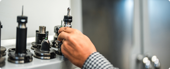
How Does Multi-Axis CNC Machining Work?
In a multi-axis environment, the CNC controller coordinates movement across multiple linear and rotary axes at the same time.
This demands advanced CAD/CAM programming, reliable post-processing, and a thorough understanding of the machine’s specific kinematics.
As the number of axes increases, so does the level of risk. Programmers must carefully manage factors such as potential collisions, axis travel limits, tool orientation, and machine behaviour throughout the entire machining cycle.
What are the Main Types of Multi-Axis Machining?
3-Axis CNC Machining
This is the simplest CNC configuration, with motion limited to the three linear axes (X, Y and Z).
It’s well suited to prismatic components, but less effective when dealing with complex undercuts or multi-surface geometry.
4-Axis CNC Machining
A 4-axis setup introduces a rotary axis, enabling the workpiece to rotate and allowing access to multiple faces without the need for refixturing.
This approach is commonly used for “around-the-part” milling operations.
5-Axis CNC Machining
5-axis machining supports either indexed (3+2) positioning or full simultaneous movement across five axes.
It excels at producing complex shapes, deep pockets and tight tolerances, but achieving reliable results depends on advanced CAM strategies and accurate post-processing.
6-Axis CNC Machining
With an additional axis, 6-axis machining delivers even greater flexibility — along with increased programming complexity.
It is typically used in highly automated environments, hybrid manufacturing processes (such as additive and subtractive combinations), or applications requiring extreme contouring.
As with 5-axis machining, robust CAM software and sophisticated post-processing are essential.
What are the Benefits of Multi-Axis Machining?
Fewer Setups
Saving time, extending tool life, and lowering the risk of errors.
Improved Accuracy
Enables complex features and components to be machined in a single, controlled operation.
Shorter Lead Times
Speeds up production, helping parts reach the market sooner and improving overall profitability.
Superior Surface Finish
Delivers smoother results, reducing reliance on manual finishing and rework.
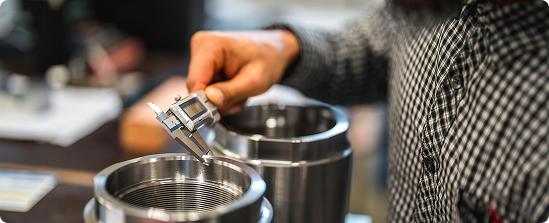
The Top 7 Programming Mistakes in Multi-Axis Machining.
Multi-axis machining is one of the most powerful tools available in modern manufacturing — but it’s also an area where mistakes can be costly.
Coordinating multiple axes, managing tool orientation, and accounting for real machine behaviour all require a high level of accuracy. A single oversight can quickly result in scrapped parts, damaged tooling, or unplanned downtime.
The positive news is that these common multi-axis programming issues are well understood — and, with the right approach, entirely preventable using Vericut.
1. Incorrect Post-Processor Configuration
The post-processor acts as the critical link between your CAM system and the CNC machine.
If it doesn’t accurately represent the machine’s true kinematics, rotary axis directions, or travel limits, even a well-designed toolpath can behave unpredictably on the shop floor. The result may be collisions, gouging, or inefficient machining cycles.
Vericut verifies the actual post-processed G-code rather than just the CAM toolpath, allowing you to see exactly how the program will run on your specific machine before pressing cycle start.
2. Inadequate Machine Simulation
Many programmers rely on the simulation tools built into their CAM software, but these typically show an idealised version of the machining process. They often fail to account for controller behaviour, acceleration and deceleration limits, or the interaction between axes under real cutting conditions.
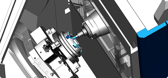
Without full G-code verification, small issues can go unnoticed. Vericut’s digital twin technology mirrors your real machine, controller, tooling, and setup to detect collisions, overtravel, and unintended axis movements before they reach the machine.
3. Poor Tool Orientation Control
In multi-axis machining, even slight errors in tool tilt, lead, or lag angles can negatively affect surface quality and tool stability.
Abrupt orientation changes can also introduce chatter or cause gouging. By simulating full 5-axis and 6-axis motion, Vericut allows you to review and refine every movement, ensuring smooth transitions and stable cutting angles across complex geometries.
4. Ignoring Machine Travel Limits
Every multi-axis machine has fixed travel limits and potential problem areas, such as kinematic singularities, where smooth motion becomes difficult for the control system to calculate.
Failing to account for these constraints can result in sudden axis wind-up, erratic motion, or unexpected rotations that put parts and tooling at risk. Vericut highlights these issues visually, enabling programmers to adjust toolpaths, reposition the part, or modify setups before any material is cut.
5. Misaligned Work Coordinate System
An incorrect work coordinate system can turn an otherwise flawless program into instant scrap by positioning the part incorrectly on the machine.
These errors often stem from incorrect fixture offsets, probing routines, or setup data. Vericut simulates the complete machining environment — including fixtures, offsets, and part orientation — so you can confirm the WCS matches both the CAD model and machine configuration before production begins.
6. A Lack of Toolpath Optimisation
Multi-axis toolpaths are often lengthy and highly detailed, containing many small linear moves or sudden changes in feed rate.
This can place unnecessary stress on the cutting tool, shorten tool life, and lead to inconsistent surface finishes. Vericut Force analyses real material removal and automatically optimises feed rates to deliver smoother motion, consistent cutting forces, and ideal chip loads.
7. Unsuitable Tool and Holder Selection
Even with accurate toolpaths, an inappropriate tool or holder can cause clearance problems or collisions — particularly in tight, multi-axis applications.
Overly long holders or inaccurately modelled tool geometry may only reveal issues once machining has started. With Vericut’s comprehensive tool and holder libraries and full collision detection, you can validate the entire cutting assembly in a virtual environment and make adjustments before running the job on the machine.
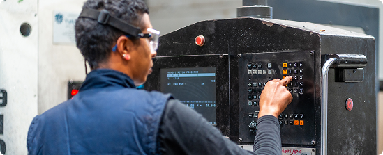
Why Multi-Axis Machine Simulation with Vericut Matters.
In today’s highly advanced CNC manufacturing environment, errors in multi-axis programming are more than an inconvenience — they can be costly and disruptive.
As component designs become more complex and tolerances and delivery schedules tighten, Vericut CNC simulation and verification software helps close the gap between CAM output and real-world machining. By validating toolpaths at the G-code level, Vericut provides confidence that programs will run exactly as intended on the machine.
From aerospace and motorsport to medical device manufacturing and industrial engineering, organisations worldwide rely on Vericut to:
-
Avoid expensive machine crashes and unplanned downtime
-
Confirm true machine kinematics against actual machine behaviour
-
Optimise toolpaths for improved speed, efficiency, and reliability
-
Support complex multi-axis and automated machining with confidence
Discover Vericut Multi-Axis Simulation today.
Explore Vericut’s Multi-Axis CNC Simulation solutions to avoid these programming mistakes, and help protect your people, products, and profits.
-1.jpg)