English - United Kingdom
 English - Singapore
 한국어 - 대한민국

Multi-axis machining has transformed modern manufacturing, enabling machine shops across the world to produce complex geometries in fewer setups, with greater accuracy and efficiency.
Whether it’s a 4-axis rotary job, or a full simultaneous 5- or 6-axis operation, these machines can be game-changers for your productivity and profitability.
But with increased capability comes increased complexity. Even skilled programmers can encounter problems, leading to costly scrapped parts and material, damaged tooling, machine downtime, and production delays.
In this blog, we’ll explore the top seven programming mistakes in multi-axis machining, and how simulation and verification with Vericut can help you avoid them.

What is Multi-Axis Machining?
Multi-axis machining solutions use CNC equipment that’s capable of moving a cutting tool or workpiece along more than the traditional three linear axes (X, Y, Z).
By adding rotational movement (A, B, or C axes), manufacturers can machine intricate geometries and surfaces in fewer setups, often in one continuous cycle.
From aerospace turbine blades to custom medical implants, multi-axis machining makes previously impossible parts achievable with precision.

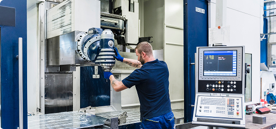
How Does Multi-Axis CNC Machining Work?
In a multi-axis setup, the CNC controller synchronizes movement across multiple linear and
rotary axes simultaneously.
This requires sophisticated CAD-CAM programming, accurate post-processing, and a
complete understanding of the machine’s unique kinematics.
The more axes in play, the more factors and risks programmers must account for, such as a
collision, axis travel limits, and tool orientation.
What are the Main Types of Multi-Axis Machining?
3-Axis CNC Machining
This is the most basic setup, with movement along the three linear axes (X, Y, and Z).
It’s ideal for prismatic parts, but limited for complex undercuts or compound surfaces.
4-Axis CNC Machining
This process adds a rotary axis, typically allowing workpieces to be rotated to access multiple sides without refixturing.
It’s optimal for “around-the-part” milling.
5-Axis CNC Machining
This offers either indexed (3+2), or fully simultaneous movement, across five axes.
It’s perfect for complex geometries, deep cavities, and tight tolerances, but for optimal results, it requires advanced CAM strategies and post-processing.
6-Axis CNC Machining
This introduces even more machining flexibility and, by extension, complexity.
It is often used for automation, hybrid manufacturing (e.g., additive + subtractive), or for parts requiring extreme contouring.
Again, like 5-Axis, advanced CAM systems and post-processing are a must.
What are the Benefits of Multi-Axis Machining?
Fewer Setups
Saves time, preserves tool life, and reduces errors.
Improved Accuracy
Machine complex features and components in one cycle.
Shorter Lead Times
Gets parts to market faster, improving profits.
Superior Surface Finish
Reduces the need for error-prone hand finishing.

The Top 7 Programming Mistakes in Multi-Axis Machining.
As you can see, multi-axis machining is one of the most powerful capabilities in modern manufacturing, but it’s also one of the easiest places to trip up.
Synchronizing multiple axes, controlling tool orientation, and accounting for real machine behavior demand absolute precision, and a single misstep can lead to costly consequences.
The good news is that these multi-axis programming pitfalls are predictable, and, more importantly, avoidable with Vericut.
1. Incorrect Post-Processor Configuration
The post-processor is the vital bridge between your CAM system and the CNC machine.
If it’s not configured to accurately reflect your machine’s real kinematics, rotary directions, or axis limits, even an exceptional CAM toolpath can behave unpredictably in practice.
This can lead to tool collisions, gouging, or wasted cycles.
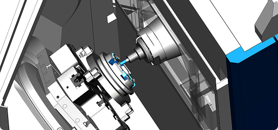
Vericut’s machine simulation verifies the post-processed G-code, not just the CAM toolpath, so you know exactly how the program will run on your specific machine before the cycle starts.
2. Inadequate Machine Simulation
Many programmers rely solely on their CAM system’s built-in simulation, but this only shows an idealized representation. It often ignores controller-specific behaviors, acceleration limits, or the interplay between axes under load.
Without full G-code verification, subtle errors can slip through. Vericut’s digital twin technology mimics your machine, controller, and setup exactly, detecting collisions, overtravel, and even unintended axis flips before they happen.
3. Poor Tool Orientation Control
In multi-axis machining, even a minor error in tool tilt, lead, or lag angle can affect surface quality, or create tool instability.
Sudden orientation changes may also introduce chatter or gouges. With Vericut’s simulation of 5-axis and 6-axis motion, you can check and refine every movement, ensuring smooth transitions and stable cutting angles across complex surfaces.
4. Ignoring Machine Travel Limits
Every multi-axis machine has hard travel limits and potential problem zones, such as kinematic singularities, where the control system struggles to calculate a smooth path.
Ignoring these can result in sudden axis “wind-up,” jerky movement, or unexpected rotations that risk the part or tooling. Vericut highlights these risks visually so programmers can adjust toolpaths, reorient the part, or tweak setups before a single chip is cut.
5. Misaligned Work Coordinate System
A WCS error can ruin an otherwise perfect program, misplacing the part by a few millimeters, and causing immediate scrap.
This can happen when fixture offsets, probing routines, or setup data are entered incorrectly. Vericut simulates the complete part setup, including fixtures and offsets, so you can confirm that your WCS matches both the CAD model and machine expectations before production.
6. A Lack of Toolpath Optimization
Multi-axis toolpaths can be long and complex, often containing small linear segments, or sharp changes in feed rate.
This can overload the cutter, reduce tool life, and create inconsistent finishes. Vericut Force analyzes the actual material removal process, automatically adjusting feed rates for smoother motion, consistent cutting forces, and optimal chip loads.
7. Unsuitable Tool and Holder Selection
Even if your toolpaths are theoretically perfect, the wrong tool assembly can cause clearance issues or collisions, especially in tight, multi-axis operations.
Plus, if a tool holder is too long, or a tool geometry isn’t accurately modeled, you may only discover the problem mid-cut.
With Vericut’s extensive tool and holder libraries and full collision checking, you can validate the complete cutting assembly in the virtual environment and make adjustments before going live.

Why Multi-Axis Machine Simulation with Vericut Matters.
In today’s ultra-sophisticated CNC manufacturing, multi-axis programming errors aren’t just inconvenient: they’re expensive and timely.
With rising complexity in component craft, and tighter tolerances and deadlines to meet, Vericut CNC simulation and verification software bridges the gap between your CAM and your machining reality, validating your toolpaths at the G-code level for complete confidence.
From aerospace and motorsport, to medical device production and industrial engineering, manufacturers across the globe trust Vericut to:
- Prevent costly machine crashes and downtime.
- Verify true kinematics against real machine movements.
- Optimize toolpaths for speed, efficiency, and assurance.
- Enable multi-axis and automated machining with confidence.
Discover Vericut Multi-Axis Simulation today.
Explore Vericut’s Multi-Axis CNC Simulation solutions to avoid these programming mistakes, and help protect your people, products, and profits.